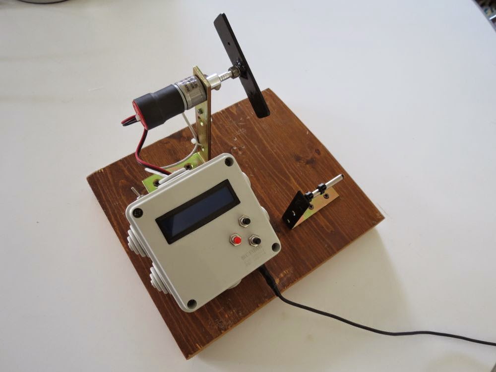
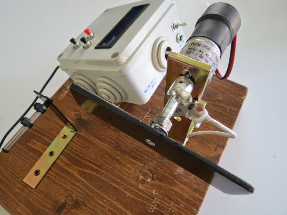
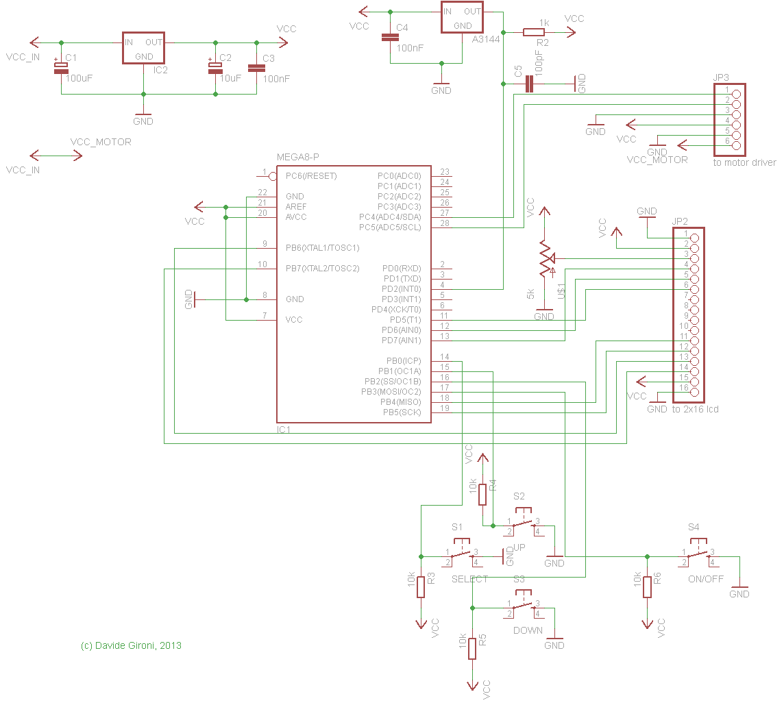
The core of this project is an ATmega8.
It features:
- wind counter
- slow startup
- automatic stop
- configurable motor speed
- configurable winds
- 2 directions
This winder has an LCD display that will show
- the current motor direction
- the rotating speed of your pickup
- the total and current wind counter
- motor direction - clockwise, or anti-clockwise
- direction of the wind counter to increase - clockwise, or anti-clockwise
- motor max speed - from 1(min) to 100 (max)
- motor startup accelleration - from 1(min) to 100 (max)
- numbers of wind - from 1(min) to 99999 (max)
- auto stop mode - manual mode, or stop when all winds are done
To enter the programming mode, just long press SELECT button.
Press SELECT once to change the programming parameter, button UP and DOWN to edit the selected value, then long press SELECT again to save new values.
If you are in building mode, to make the wind start press the RUN pedal, it will start with a slow startup, to stop the winder release the RUN pedal.
Long press butto UP to change direction.
Long press butto DOWN to reset counter.
The winding machine will automatically stops when the wind counter reach the configured number, and it can goes less than zero
If you disable the autostop mode, the machine will always count wind, independently by the direction choosen.
The motor used is cheap DC motor 12V 1200rpm, the motor driver is L298N chip board.
This library was developed on Eclipse, built with avr-gcc on ATmega8 @ 8MHz.
ChangeLog
- 01b: fix a circut file typo error in the LCD connection of previous version.
- 01: first version.
Code
- avr_pickupw_01b.zip (source and hex compiled for ATmega8 @ 8Mhz)
avr_pickupw_01.zip (source and hex compiled for ATmega8 @ 8Mhz)
Notes
- read risk disclaimer
- excuse my bad english


Bravo, interessante, ci proverò (un dì).
ReplyDeleteGrazie :)
Deletewhich was magnet used in the hall sensor?
ReplyDeleteThe hall sensor is a A3144, the manget it's a circle one, almost 2mm dimeter x 1mm height.
DeleteThanks, neodinium or ferrite magnet?
ReplyDeleteNeodymium ;)
DeleteThis comment has been removed by a blog administrator.
ReplyDeleteThis comment has been removed by a blog administrator.
ReplyDeleteVery nice project ;) Which motor you are using?
ReplyDeleteThanks!
Thank you, i'm using an ebay cheap DC motor 12V 1200rpm.
DeleteI'm also implementing an hardware PWM driver with slow startup, which eventually can drive motor smoothly.
Hello, very good project, I asked PC4 and PC5 connected to JP3, how to connect to (L298N), IN1 and IN2 connected? Thank you!
ReplyDeleteHello, if you have a L298N preassembled board, IN1 and IN2 are the motor input. If you are building your how driver, that output goes to L298N input pins for motor 1.
DeleteI want to copy this build more or less, any advice what I maybe should do differently?
ReplyDeleteThe one you see above, works. But I'm developing a new version with hardware timer controller DC motor, and eventually a guide motor, this version has not the same wiring. It has to be tested, and then i will publish it... but it will take sametimes, cause i do this type of work during sparetime.
DeleteI can't quite get it from the schematics, but what kind of screen did you use ? I'm guessing you had to use one that can actually "refresh" fast enough to display the windings.
DeleteThe one that i used is a "standard" ebay cheap 2x16 LCD HD44780 based.
DeleteHello, yes I've but it's not yet posted. Mail me if you want that version in preview.
DeleteHola.
ReplyDeleteEu nao consegui fazer funcionar. Gravei o .hex usando o PonyProg2000, mas nao aparece nada no display :(
Hello.
DeleteYou have to debug your hardware. Double check your wiring. Also if you are not using an ATmega8, re-compile the source with avrgcc.
Yes, I used the ATmega8.
DeleteCould you send me only the Hex file for I try to burn again?
Thank you. Sorry any bother.
Yes, tell me your mail.
Deletericardo.ams@live.com or ricardo.ams@gmail.com
DeleteThanks, David
You've got mail.
DeleteThis comment has been removed by the author.
DeleteHello Friend. I had given up. But I decided to do the last test, as hopeless. And amazingly it worked :) lol I had not set the bits properly.
DeleteHere is a picture of the running project, still in the testing phase:
http://i1121.photobucket.com/albums/l510/ricardoams/IMG_20150422_185327344.jpg
Here is the correct way of Bits:
http://halvar.at/elektronik/kleiner_bascom_avr_kurs/fusebits_standard/ponyprog_fuse_intern_rc_8mhz.gif
Thank you for your help.
Great, and thank you for feedback!
DeleteHello Davide, I will set up your project on a PCB.
DeleteI would ask earnestly When you have an available time, would you please make two small modifications to the code for me?
The first change would be as follows:
I use an AC motor, I have no need to control the initial speed and engine end. Instead of L298N driver would just like to be able to control a relay to turn on and turn off the engine.
The second change would be in the form of selecting the number of turns, for I have difficulties in placing an exact number of turns eg (4950) I end up taking a while to get these numbers on the display.
My suggestion would be if you could select a digit at a time and change them individually.
I hope I've been able to explain and hope you can help me.
Thank you very much for providing this magnificent project.
A big hug from Brazil.
This comment has been removed by a blog administrator.
DeleteHello,
DeleteMost of the time using a simple relay as to start/stop the AC motor is a problem, due to the cable thickness it brokes if stressed by a fast start. Anyway, you can do a instant start using a relay removing all the dcmotorpwmsoft function reference and using just one pin as output (as example: DDRC |=(1<<PC4)), and starting it on and off insted of using the dcmotorpwmsoft_gostop, dcmotorpwmsoft_goforward, dcmotorpwmsoft_gobackward, (es. PORTC |= (1 << PC4); or PORTC &= ~(1 << PC4);). Or you can use some mosfet in h-bridge configuration if you can not find the L298N.
About the number of turn, thank for suggestion, it could be done even if with only 3 buttons it's a bit triky. For now, you should get next to your number you need long pressing the select button, then single press the buttons to get the right number. IT you want a slower turn up/down on long press, remove the lines that increment or decrement by 1000 the number in the "set_plusminus" function, making it look like this: http://pastebin.com/uxkv36bm.
Hello, thanks for the tutorial, but I looked at your code and do not know which changes the number of turns? I need to roll up 700 laps on a reel to the reel, but not figure out how to do this would increase through the buttons? a hug
ReplyDeleteHow to set the number of laps that the motor will spin?
Turns - turns
Thank you
Hello, the number of turns can be setted by the menu. Long press the Select button to enter the setup, then click Select button and go to "Wind" section, set the number of turn here. Long press Select button again to store that number.
DeleteThank you for answering me, a hug
DeleteThis comment has been removed by the author.
DeleteThis comment has been removed by the author.
DeletePlease help me, I am beginner and need to know the following: You said: This library was developed in Eclipse, built with avr-gcc in ATmega8 @ 8MHz.
DeleteI will install this library, where teak? in eclipse? I think to record the ATmega8 in PONY, how would I do? ppor please answer.
Hello, you can find a few tutorial online, teaching you how to intall and use Eclipse with AVR, unlucky is not something to write down in a 5 line comment answer.
DeleteThis comment has been removed by a blog administrator.
ReplyDeleteHi Davide, what is IC2 in schematics?
ReplyDeleteHello, 5V voltage reg, like 7805. This upper part is just a regulator, you can use any other regulator if you want.
DeleteCan it work with Arduino Uno? instead Atmega8
DeleteHello David, yes it could but you have to refactor some code cause ATmega328 has slightly different registers.
DeleteHi davide Gironi Could you send me only the Hex file for I try to burn?
ReplyDeleteHi davide Gironi Could you send me only the Hex file for I try to burn?
Deleteagungsupadma84@gmail.com
Hello, you've got mail.
DeleteHello!
ReplyDeleteThe project was great.
1. You ask me, can this project count down, for example if I turn back, it count down?
2. An example of a running power failure would be if it had saved the winding number.
Thank you very much !
Hello. This can not count down.
DeleteThis comment has been removed by a blog administrator.
ReplyDeletePlease list the parts to build :))
ReplyDeleteHello, as for the electronics, you can find the full schematics in the post .zip. The bom part is there. The other main part is the motor, mine was a motor 12V 1200rpm.
Delete